SAP2000 tutorial course for beginners - 5: Analysis and design of frames
Introduction:
This is the fifth SAP2000 tutorial, at the end of this tutorial you'll be able to make a full structural analysis of any frame which contains columns and beams, and trusses which is more complicated than the beams that we took in SAP2000 tutorial No. 4, and to display shear and moment diagrams as well.
Solving 2D frames Using blank template:
2D frames can easily be defined and analyzed using SAP 2000. This part of sap handout is to make user practice different tools in the program.Example 1:
1-Draw axial, shear, bending moment diagrams for 2D frame shown in figure 1.
2- Find reactions at support: A, B using SAP.
 | |
|
1- Define appropriate grid system; frame is in the xz plan. The appropriate system consists of 2 spacing in the z direction and one space in the x direction (see figure 2).
 | |
|
2- Draw the beams (using the default section since self-weight will not be considered) and assign supports as shown in figure 3.
 | |
|
3- Select horizontal beam, vertical beam respectively and assign the loads as shown in figure 4.
 | |
|
4- User now must have the same display shown in figure 5.
 | |
|
5- To neglect self-weight make sure you modify the self-weight multiplier to zero value.
6- Now analyze the model (hit F5).
7- Display: axial, shear, moment diagrams (see figure 6).
 | |
|
8- To Display reactions at points: A, B as required in example, do the following steps:
Display ➥ Show Forces/Stresses ➥ joints (see figure 7).
 | |
|
Solving 2D frames Using frame template:
Example 2: Create the previous structural system using frame template. 1- File ➥ new model ➥ 2D frames (see figure 8).
 | |
|
2- Make sure you have the same input shown in figure 9+10.
 | |
|
 | |
|
3- Make the suitable changes to get as what is shown in figure 11.
 | |
|
Example 3:
1-Draw axial, shear, bending moment diagrams for 2D frame shown in figure 12.
2- Find reactions at support: A, B using SAP.
 | |
|
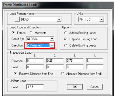
1- Define the suitable grid system to represent this system, OR using frame template represent the system. 2- The main idea in this problem is how to represent gravity distributed load in the same way; to do this user can define it in two ways:
A) Alternative # 1: 1- after drawing the structural system (figure 13) select the inclined beam.
 | |
|
2- Assign ➥ Frame loads ➥ Distributed (see figure 14).
 | |
|
3- Continue defining loads and analyze the system.
B) Alternative # 2: this way is manual analysis of the force. Figure 15 shows how load is treated: two components; one is parallel to the element and the other is perpendicular to it.
 | |
|
This way requires defining two distributed loads; the first is 15.593 KN/m perpendicular to the element and 5.457 KN/m axially.
Following steps must be followed to define these loads:
1- show the local axis of the inclined element. To do so do as shown in figure 16.
 | |
|
2- Look at figure 17. White color stands for “local axis 2” and red stands for “local axis 1”. Note the orientation of local axis to use the suitable sign in defining the loads.
 | |
|
3- User will define loads on inclined beam at two stages. Stage one: Select the inclined beam, then assign ➥ frame loads ➥ distributed (see figure 18).
 | |
|
4- Repeat steps mentioned previously in point 3. See figure 19.
 | |
|
5- Compare results of two alternatives to check answers.
Solving 2D Trusses Using blank template: Building a simple 2D truss does not differ widely than a simple frame. First you need to create the appropriate grid system.
Example 1: 1- Determines the required grid system required to build this system. Remember that this truss lays in xz plan. In this case use 4 spacing in x and 1 spacing in z (see figure 1).
 | |
|
2- Draw the elements shown in figure 2. Remember to draw each segment separately.
 | |
|
3- AB & BC (in figure 1) must be divided in two segments. To do this select both members by clicking on them then: Edit ➥ Edit lines ➥ divide frames (see figure 3).
 | |
|
4- Continue drawing remaining elements so you can have the full required geometry. Assign pin supports (see figure 4).
 | |
|
5- Since trusses members are connected through hinges, a change must be done to each start and end of a member. To do so select an element ➥ Assign ➥ Frame ➥ Releases/partial fixity ➥ release M33 at start and end (see figure 5).
 | |
|
6- Repeat this to each one element. Remember multi-selection option is available. Finally you must have the same result as shown in figure 6.
 | |
|
7- Assign the loads on joints (see figure 7).
Remember to neglect self-weight.
 | |
|
8- Run analysis by hitting F5.
9- Display reactions at joints (see figure 8).
 | |
|


No comments: